Registrations
We now manually approve all new user accounts due to a large influx of spam bots. Accounts are normally approved within 48 hours.
If you need any help with using this Wiki, please ask here: TalkFord.com Wiki Submission Forum
Difference between revisions of "Intake Manifold Removal"
Compuwiz uk (Talk | contribs) (→Removal) |
m (→Duratec HE Intake Manifold Removal Procedure) |
||
| (9 intermediate revisions by 3 users not shown) | |||
| Line 1: | Line 1: | ||
| + | {{note|'''The Ford Mondeo hit our roads in 1993, and has consistently been a sales success. Now on its 4th incarnation, it remains a drivers favourite.'''<br> | ||
| + | '''For more information, visit the [http://www.talkford.com/forum/596-mondeo/ Ford Mondeo] forum on [http://www.talkford.com TalkFord.com], the definitive resource site covering all Fords from the present day to the 1970's.'''}} | ||
| + | ---- | ||
| + | {{Infobox | ||
| + | |name = Infobox Template | ||
| + | |bodystyle = float:right; valign:top; | ||
| + | |image = [[File:Fordwiki infobox.png]] | ||
| + | |imagestyle = | ||
| + | |caption = Overview Guide | ||
| + | |captionstyle = | ||
| + | |headerstyle = background:#ccf; | ||
| + | |labelstyle = background:#ddf; | ||
| + | |datastyle = text-align:right; | ||
| + | |header1 = | ||
| + | |label1 = Ford Model: | ||
| + | |data1 = '''Mondeo''' | ||
| + | |header2 = | ||
| + | |label2 = Petrol/Diesel: | ||
| + | |data2 = '''????''' | ||
| + | |header3 = | ||
| + | |label3 = Estimated Cost: | ||
| + | |data3 = '''????''' | ||
| + | |header4 = | ||
| + | |label4 = Difficulty? | ||
| + | |data4 = '''????''' | ||
| + | |label5 = How long does this take? | ||
| + | |data5 = '''????''' | ||
| + | }} | ||
| + | |||
== Duratec HE Intake Manifold Removal Procedure == | == Duratec HE Intake Manifold Removal Procedure == | ||
| + | |||
| + | To establish if you have the failure-prone tumble flaps, see [[Inlet Manifold Fault - Duratec|this article]]. | ||
=== Removal === | === Removal === | ||
| Line 36: | Line 67: | ||
9. Detach the accelerator cable. | 9. Detach the accelerator cable. | ||
| − | + | ''1 Detach the inner cable.'' | |
| − | + | ||
| − | + | ||
| + | ''2 Turn the cable out of the bracket.'' | ||
| + | |||
Detach the cable and position it to one side. | Detach the cable and position it to one side. | ||
| Line 80: | Line 111: | ||
Detach the intake manifold from the cylinder head. | Detach the intake manifold from the cylinder head. | ||
| − | |||
[[Image:intake17.jpg]] | [[Image:intake17.jpg]] | ||
| Line 103: | Line 133: | ||
2. Initialize the door window motors. | 2. Initialize the door window motors. | ||
| + | == Duratec SCI Intake Manifold Removal Procedure == | ||
| + | |||
| + | === Removal === | ||
| + | |||
| + | 1. Disconnect the battery ground cable. | ||
| + | |||
| + | 2. Remove the engine cover. | ||
| + | |||
| + | [[Image:sci2.jpg]] | ||
| + | |||
| + | |||
| + | |||
| + | 3. Remove the air cleaner inlet hose. | ||
| + | |||
| + | [[Image:sci3.jpg]] | ||
| + | |||
| + | |||
| + | |||
| + | 4. Raise the vehicle. | ||
| + | |||
| + | 5. Remove the oil dipstick tube lower bolt. | ||
| + | |||
| + | [[Image:sci5.jpg]] | ||
| + | |||
| + | |||
| + | |||
| + | 6. Remove the intake manifold lower bolt. | ||
| + | |||
| + | [[Image:sci6.jpg]] | ||
| + | |||
| + | |||
| + | |||
| + | 7. Detach the starter motor connector. | ||
| + | |||
| + | [[Image:sci7.jpg]] | ||
| + | |||
| + | |||
| + | |||
| + | 8. Lower the vehicle. | ||
| + | |||
| + | 9. Remove the power steering pump. | ||
| + | |||
| + | 10. Remove the coolant pump pulley. | ||
| + | |||
| + | [[Image:sci10.jpg]] | ||
| + | |||
| + | |||
| + | |||
| + | 11. Detach the intake manifold wiring harness connector. | ||
| + | |||
| + | ''Unclip the wiring harness.'' | ||
| + | |||
| + | [[Image:sci11.jpg]] | ||
| + | |||
| + | |||
| + | |||
| + | 12. Remove the oil dipstick and tube. | ||
| + | |||
| + | [[Image:sci12.jpg]] | ||
| + | |||
| + | |||
| + | |||
| + | 13. Detach the throttle valve housing from the intake manifold. | ||
| + | |||
| + | [[Image:sci13.jpg]] | ||
| + | |||
| + | |||
| + | |||
| + | 14. Detach the manifold absolute pressure (MAP) sensor connector. | ||
| + | |||
| + | [[Image:sci14.jpg]] | ||
| + | |||
| + | |||
| + | |||
| + | 15. Detach the canister purge solenoid valve from the intake manifold. | ||
| + | |||
| + | [[Image:sci15.jpg]] | ||
| + | |||
| + | |||
| + | |||
| + | 16. Detach the brake servo vacuum line from the intake manifold. | ||
| + | |||
| + | [[Image:sci16.jpg]] | ||
| + | |||
| + | |||
| + | |||
| + | 17. Detach the swirl plate servo motor connector. | ||
| + | |||
| + | [[Image:sci17.jpg]] | ||
| + | |||
| + | |||
| + | |||
| + | 18. Detach the swirl plate position sensor connector. | ||
| + | |||
| + | ''Unclip the wiring harness.'' | ||
| + | |||
| + | [[Image:sci18.jpg]] | ||
| + | |||
| + | |||
| + | |||
| + | 19. Detach the connector from the A/C compressor clutch. | ||
| + | |||
| + | [[Image:sci19.jpg]] | ||
| + | |||
| + | |||
| + | |||
| + | 20. Detach the thermostat connector. | ||
| + | |||
| + | [[Image:sci20.jpg]] | ||
| + | |||
| + | |||
| + | |||
| + | 21. Detach the knock sensor (KS) connector for cylinders 1 and 2. | ||
| + | |||
| + | [[Image:sci21.jpg]] | ||
| + | |||
| + | |||
| + | |||
| + | 22. Disconnect the exhaust gas recirculation (EGR) pipe from the EGR valve. | ||
| + | |||
| + | ''Discard the gasket.'' | ||
| + | |||
| + | [[Image:sci22.jpg]] | ||
| + | |||
| + | |||
| + | |||
| + | 23. Disconnect the EGR pipe from the intake manifold. | ||
| + | |||
| + | ''Discard the gasket.'' | ||
| + | |||
| + | [[Image:sci23.jpg]] | ||
| + | |||
| + | |||
| + | |||
| + | 24. Remove the intake manifold bolts. | ||
| + | |||
| + | [[Image:sci24.jpg]] | ||
| + | |||
| + | |||
| + | |||
| + | 25. Disconnect the PCV hose from the intake manifold. | ||
| + | |||
| + | [[Image:sci25.jpg]] | ||
| + | |||
| + | |||
| + | |||
| + | 26. Remove the intake manifold. | ||
| + | |||
| + | |||
| + | === Installation === | ||
| + | |||
| + | 1. Note: | ||
| + | Clean the intake manifold gasket and check it for damage. If necessary install a new intake manifold gasket. | ||
| + | |||
| + | Note: | ||
| + | Clean the throttle valve housing gasket and check it for damage. If necessary install a new intake manifold gasket. | ||
| + | |||
| + | Install the components in the reverse order. | ||
| + | |||
| + | 2. Initialize the window winder motors. | ||
| − | [[Category: | + | [[Category:Mondeo_Mk3]] |
Latest revision as of 18:26, 22 April 2011
For more information, visit the Ford Mondeo forum on TalkFord.com, the definitive resource site covering all Fords from the present day to the 1970's.
|
Overview Guide | |
| Ford Model: | Mondeo |
|---|---|
| Petrol/Diesel: | ???? |
| Estimated Cost: | ???? |
| Difficulty? | ???? |
| How long does this take? | ???? |
Contents
Duratec HE Intake Manifold Removal Procedure
To establish if you have the failure-prone tumble flaps, see this article.
Removal
1. Detach the positive crankcase ventilation (PCV) hose and the vacuum hose from the engine upper cover.
2. Remove the engine upper cover.
3. Disconnect the battery ground cable.
4. Raise and support the vehicle.
5. Remove the oil level indicator lower retaining bolt.
6. Remove the intake manifold lower retaining bolt.
7. Lower the vehicle.
8. Detach the air cleaner outlet pipe from the throttle body (TB).
9. Detach the accelerator cable.
1 Detach the inner cable.
2 Turn the cable out of the bracket.
Detach the cable and position it to one side.
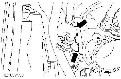
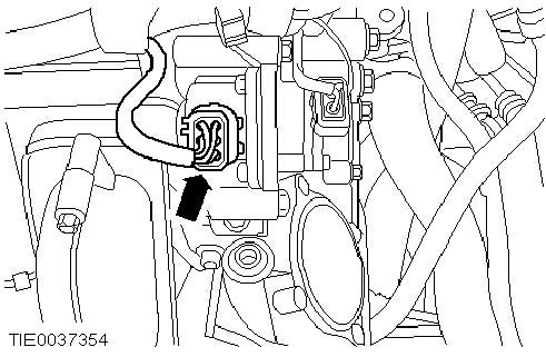
10. Disconnect the throttle position (TP) sensor and the idle air control (IAC) valve electrical connectors.
11. Disconnect the brake booster vacuum line from the intake manifold.
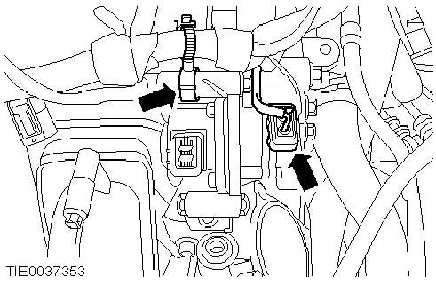
12. Disconnect the electrical connectors.
13. Detach the engine wiring harness from the intake manifold.
14. Remove the oil level indicator and tube.
15. Disconnect the vacuum hoses from the intake manifold.
16. Disconnect the engine air shut off valve, the manifold absolute pressure (MAP) sensor and the swirl plates solenoid valve electrical connectors.
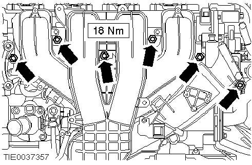
17. Remove the intake manifold bolts (engine shown removed for clarity).
Detach the intake manifold from the cylinder head.
18. Disconnect the PCV hose from the intake manifold.
19. Detach the knock sensor (KS) electrical connector from the intake manifold.
20. Remove the intake manifold.
Installation
1. Note: Install new gaskets.
To install, reverse the removal procedure.
2. Initialize the door window motors.
Duratec SCI Intake Manifold Removal Procedure
Removal
1. Disconnect the battery ground cable.
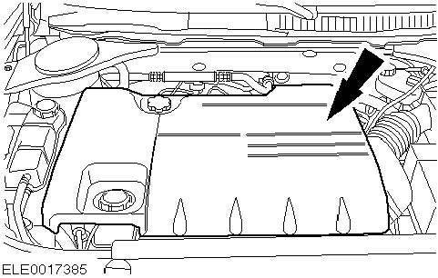
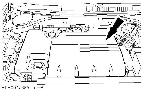
2. Remove the engine cover.
3. Remove the air cleaner inlet hose.
4. Raise the vehicle.
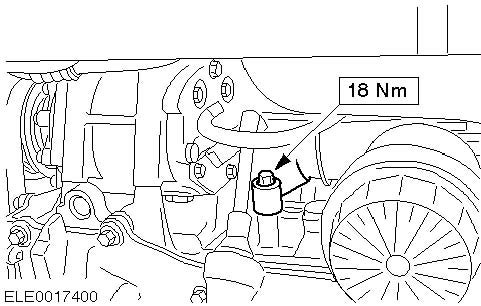
5. Remove the oil dipstick tube lower bolt.
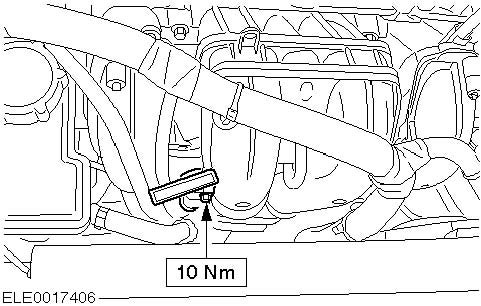
6. Remove the intake manifold lower bolt.
7. Detach the starter motor connector.
8. Lower the vehicle.
9. Remove the power steering pump.
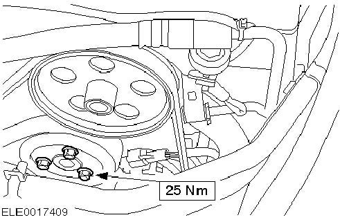
10. Remove the coolant pump pulley.
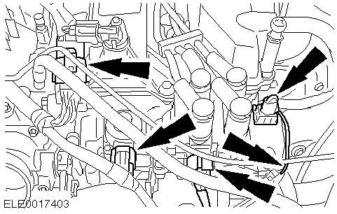
11. Detach the intake manifold wiring harness connector.
Unclip the wiring harness.
12. Remove the oil dipstick and tube.
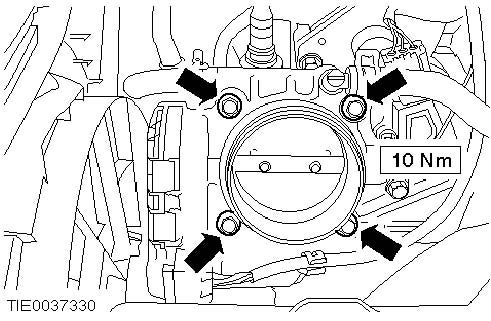
13. Detach the throttle valve housing from the intake manifold.
14. Detach the manifold absolute pressure (MAP) sensor connector.
15. Detach the canister purge solenoid valve from the intake manifold.
16. Detach the brake servo vacuum line from the intake manifold.
17. Detach the swirl plate servo motor connector.
18. Detach the swirl plate position sensor connector.
Unclip the wiring harness.
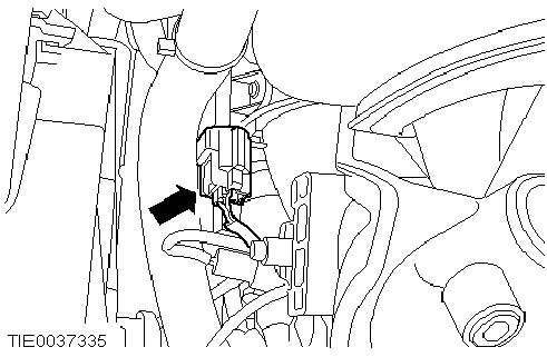
19. Detach the connector from the A/C compressor clutch.
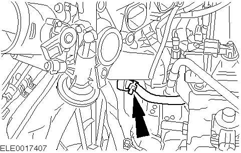
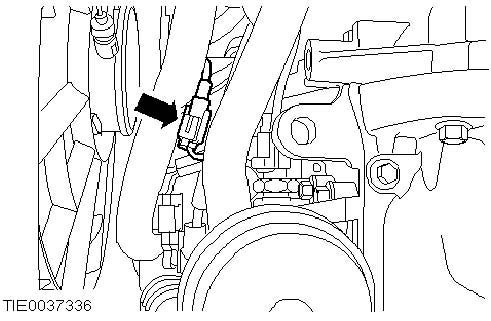
20. Detach the thermostat connector.
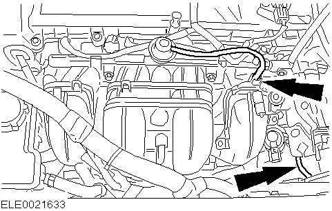
21. Detach the knock sensor (KS) connector for cylinders 1 and 2.
22. Disconnect the exhaust gas recirculation (EGR) pipe from the EGR valve.
Discard the gasket.
23. Disconnect the EGR pipe from the intake manifold.
Discard the gasket.
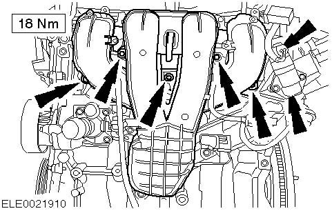
24. Remove the intake manifold bolts.
25. Disconnect the PCV hose from the intake manifold.
26. Remove the intake manifold.
Installation
1. Note: Clean the intake manifold gasket and check it for damage. If necessary install a new intake manifold gasket.
Note: Clean the throttle valve housing gasket and check it for damage. If necessary install a new intake manifold gasket.
Install the components in the reverse order.
2. Initialize the window winder motors.













 Your Privacy Choices