Registrations
We now manually approve all new user accounts due to a large influx of spam bots. Accounts are normally approved within 48 hours.
If you need any help with using this Wiki, please ask here: TalkFord.com Wiki Submission Forum
Difference between revisions of "Injector Cleaning"
Peter scott (Talk | contribs) |
Peter scott (Talk | contribs) |
||
| Line 45: | Line 45: | ||
[[File:Size.jpg]] | [[File:Size.jpg]] | ||
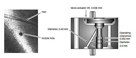
| − | The passages and jets in the injectors are small and easily blocked and the clearances between moving parts are also very small so it is essential that you work in a clean environment. (Note: The upper part of the injector shown below differs slightly from our injectors.) | + | The passages and jets in the injectors are small and easily blocked and the clearances between moving parts are also very small so it is essential that you work in a clean environment. It's not necessary to separate the nozzle from the surrounding body. (Note: The upper part of the injector shown below differs slightly from our injectors.) |
[[File:Injector_3d2.jpg]] | [[File:Injector_3d2.jpg]] | ||
Revision as of 07:17, 14 February 2013
|
Overview Guide | |
| Ford Model: | Mondeo_Mk3 |
|---|---|
| Petrol/Diesel: | Diesel |
| Estimated Cost: | ? |
| Difficulty? | Easy/Medium |
| How long does this take? | ? |
Injector Failure
Injectors fail for various reasons but the principal causes are:
Nozzle wear or clogging.
Needle tip and side wear.
Control valve wear and contamination by particles that cause jamming.
We can't do anything about wear as this requires replacement of parts that will result in the need for C2i re-characterisation which is only possible with expensive equipment but we can sort clogging and contamination.
Cleaning Procedure
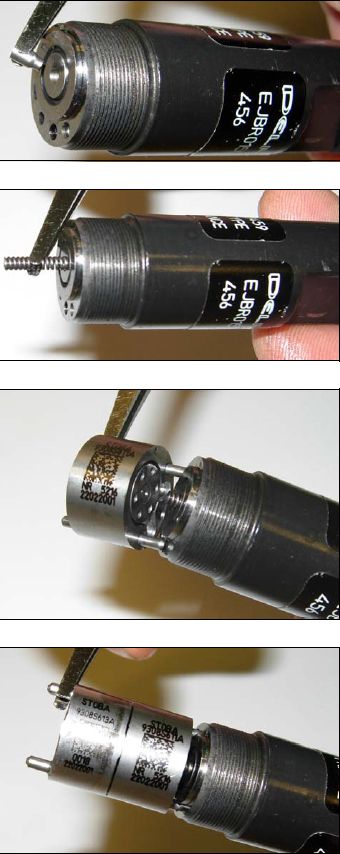
To open up the injector turn it upside down gripping the two flats in a vice so that the nozzle is pointing vertically upwards then apply a socket or ring spanner to the nozzle nut. Once you've slackened it lay it horizontally on a piece of clean white paper (so that you can easily see the small parts)
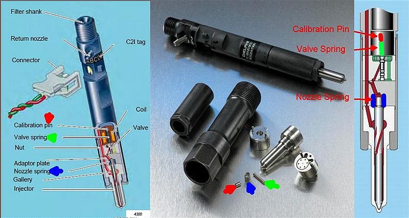
The passages and jets in the injectors are small and easily blocked and the clearances between moving parts are also very small so it is essential that you work in a clean environment. It's not necessary to separate the nozzle from the surrounding body. (Note: The upper part of the injector shown below differs slightly from our injectors.)
Note the sequence of parts.
Working up from the calibration pin down to the nozzle there is:
Calibration pin.
Valve spring
Valve
Valve body
Adaptor plate
Injector spring
Injector needle
Injector Nozzle
The calibration pin may remain in the solenoid half of the injector but be sure that it doesn't drop out and get lost.
Whilst it's important that all the above parts are clean and free from any grit or fluff I think that the most important part to get clean is the inside of the injector nozzle. This area is likely to have carbon build-up that may cause less than perfect sealing of the injector needle. Due to the fine tolerances of injector parts it's important that you don't attempt any scraping or other abrasive cleaning so that the original C2i calibration codes can be re-used.
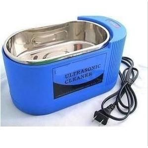
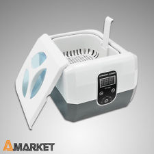
The only way of cleaning the parts effectively is to use an ultrasonic cleaning tank with a suitable cleaning fluid. I bought a small second hand industrial tank that has an 80 watt power rating. There are some relatively cheap tanks available new that claim a 60 watt power.
Clean all the parts except for the upper body of the injector that contains the solenoid and electrical connector.
The correct cleaning fluid is important. You have to use water based fluids for ultrasonic cleaning because at a micro level high temperatures are generated.
I used this fluid diluted 10 parts water to one part fluid: http://mistralie.co.uk/products/ultrasonic-cleaner-for-carburettors-machine-parts
http://www.youtube.com/watch?feature=player_embedded&v=BNhOQ4GxwXc
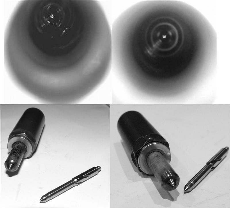
The pictures on the left are before and those on the right after 15 minutes in the cleaning tank. The difference isn't dramatic but I think you can see an improvement looking into the nozzle to where the needle sits.
My injector needle does show signs of wear where the tip seats in the nozzle but there doesn't appear to be much scoring down the sides.

If the calibration pin has a stepped diameter and been removed from the upper/solenoid part it should be replaced with the larger diameter facing the valve spring.
When re-assembling the injector it goes without saying that all the parts should be clean and dry. The locating pins in the adaptor plate and valve body should ensure correct alignment of the parts. Build the parts in the top to bottom order as below. Tighten the nozzle nut to 55 nm.
Calibration pin.
Valve spring
Valve
Valve body
Adaptor plate
Injector spring
Injector needle
Injector Nozzle
 Your Privacy Choices