Registrations
We now manually approve all new user accounts due to a large influx of spam bots. Accounts are normally approved within 48 hours.
If you need any help with using this Wiki, please ask here: TalkFord.com Wiki Submission Forum
Dash Heater Switches - Mk2 Dash - Mk1
Contents
Mk1 Dash Heater Switches - Mk2 Dash
Overview
The Mk1 and Mk2 heated window switches are technically differant in size and shape to each other. With the Mk2 connecters and switch being much larger. The back of the plugs looks similar but the internal wiring is totally differant. Both use a push non latching switch that utilises a relay to provide power to the widnscreen. Therefore most of the wiring can be similified down to a simple push to make switch and two LED/Bulbs to provide signiling to the dash. Most of the hard work is done in the fuse box and you should not need to change this to get your new switches connected.
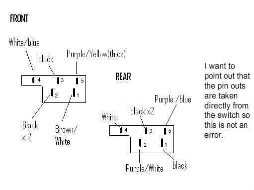
The internal wiring of the heated window switch from a 1995 reg car is shown below:

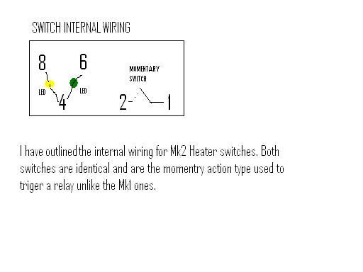
The internal wiring of the heated window switch from a Mk2 car registered later than 1987 is also shown below:

You can see from the two diagrams that the two swiches use differant pin positions although the interal electronics is very similar.
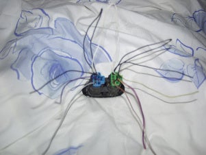
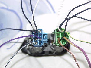
When you are purchasing your replacement Mk2 switches make sure that you also get a good length of wiring from the donour vehicle. The main reason for this is that the harness has some wires looped back to the switch . 5" should be pleanty to ensure you have theis cabling:
The basic wiring for the Mk2 plugs can be shown in the diagram below:
The Mk1 plugs is similar to this below:
The green led/light acts as a signal to show the main lights are on in the Mk2 switch. The Amber led/light a working light signal much the same as the Mk1 that shows when the heater is on. The Mk1 also had a blue light to show that the lights where on although as can be seen above does not share any similariry in its pin assinment and wiring.
The extra wiring on the Mk2 switches is actually very clever as the LEDS/Bulbs in the heater switch only have one hole to shine through . The wiring toggles each led/bulb on and off when the switch is depressed, with the lighting circuit active.
The led/bulb aray in each lights both have a comon wire this is pin three on the Mk1 and pin 4 in the MK2, Pins 1,2 transpose directly.
Ford is notorious for changing its colour coding from vehicle to vehicle with the information above you should be able to work out which wire goes where if you follow the following examples.
Heated Front Windscreen
Mk1 Wires -> Mk2 Wires
Basically this is this is the green plug on the back of the Mk2 switch. My colur codes on my socket was as follows:
Mk2 Green plug,...................................................................Mk1 colour/Pin.
Pin 1 Black , (looped back to Pin 4 on green plug)
Pin 2 Brown/white..........................................................................Brown/White, Pin 1.
Pin 3. Not connected
Pin 4. Black...................................................................................Black, Pin 3.
Pin 5. Not connected
Pin 6. Violet/yellow.........................................................................White/Blue, Pin 4
Pin 7. Not connected
Pin 8. Yellow/ Green, (White looped back to Pin 8 on Blue Plug) ........Purple/yellow, Pin 5.
Note: You will also need to connect the White cable Pin 4 from the Mkl Rear plug and connect it to Pin 8 Yellow/Green.
Note: From the old sockets that fitted the mondeo Mk1. Make sure you connect the Black x2 wires Pin 3 on the Rear heater switch socket to the Mk1 Front heated window switch sockets Black 2 wires on Pin 2.
This should allow your front windscreen to function correctly. Make sure you pay attention to the wires looped through to the blue socket.
NOTE IMPORTANT. The front heater switch only recieves power from the loom when the engine is streated and running . The switch will not recieve power the car is in this state and if you are testing ensure you do not foirget this like I did.(Took me a whole day to fathom out as had 2.3v on the power line.)
Rear Window
This is the blue connector on the back of the Mk2 switch. It is important to know these plugs should be already linked and will share some wire connections with each other. (See diagram above)
Mk2 Blue plug,......................................................................Mk1 colour/Pin.
Pin 1. Black/white..........................................................................Black x2 wires, Pin 2.
Pin 2. Brown/white , (looped back to Pin 4 on Blue plug)
Pin 3. Not connected
Pin 4. Black...................................................................................Purple/White, Pin 2.
Pin 5. Not connected
Pin 6. Violet....................................................................................White/Blue, Pin 4
Pin 7. Not connected
Pin 8. White looped back to Pin 8 on Blue Plug)
This worked for me, but I'm not responsible for anything if you want to try it...
Submitted by FULLAFFECT Re-writen and pictures added by: Max2thous10


 Your Privacy Choices