Registrations
We now manually approve all new user accounts due to a large influx of spam bots. Accounts are normally approved within 48 hours.
If you need any help with using this Wiki, please ask here: TalkFord.com Wiki Submission Forum
Centre console trim, dashboard controls and head unit removal - Mk4
For more information, visit the Ford Mondeo forum on TalkFord.com, the definitive resource site covering all Fords from the present day to the 1970's.
|
Courtesy of TalkFord.com | |
| Author: | Various |
|---|---|
| Ford Model: | Mondeo Mk4 |
| Estimated Cost: | Free |
| Difficulty? | Easy/Medium |
| How long does this take? | Varies |
This article is incomplete. Please replace or complement parts of the article highlighted in yellow.
Contents
Introduction
This article refers to Mk4 Mondeo. Majority of instructions therein reflect (and most of the images depict) first-hand experience on an early '2007 LHD vehicle. The procedure is analogous for RHD vehicles, just use the inverse (“mirror image”) imagination. It is possible that some parts and applicable removal methods on later Mk4 vehicles differ. If so, please complement this article.
Don’t let some over-scrupulous passages discourage you - trim and controls removal actually is very simple and quick task to do. Detailed description is meant to help if you’re determined to avoid eventual damage by all means and/or if you’re about to trace and eliminate cause of creaks or rattles, as described here, and would therefore like to know in detail how the parts you’re about to remove [should] look like underneath.
Numbering. Steps in the article are numbered with removal of head unit / navigation in mind. There's no numbering of steps for other tasks, e.g., for removal of controls irrelevant for access to head unit / navigation.
Steps for removal of head unit / navigation unit:
- the oval 6000CD, Sony or TravelPilot FX– follow steps (1) to (8), then proceed to either 6000CD, Sony or SD/CD Navigation TravelPilot FX (oval);
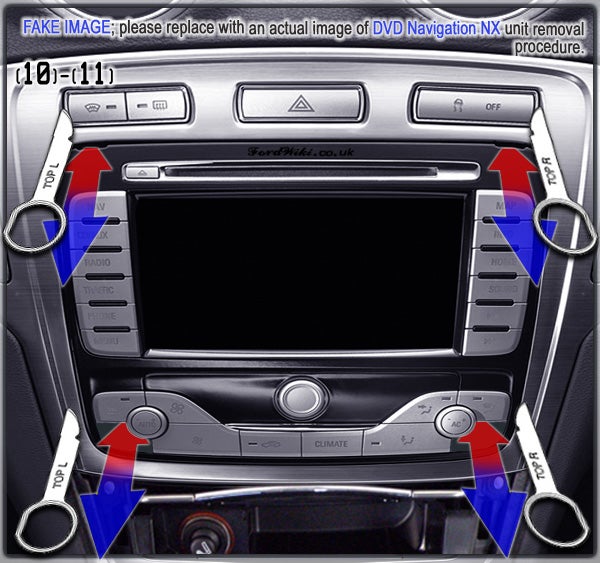
- DVD Navigation NX – follow steps (1) to (7), then proceed to DVD Navigation NX;
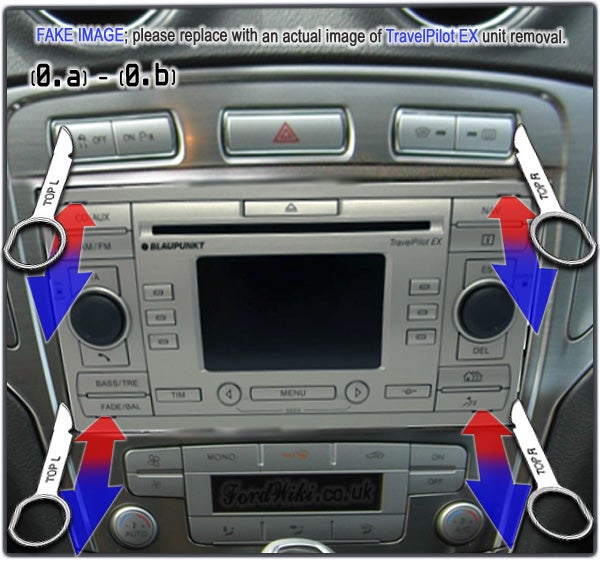
- the rectangular TravelPilot EX – only steps (0.a) to (o.c).
Steps for removal of ashtray (in order to change bulb etc.):
- on vehicles with the oval 6000CD, Sony or TravelPilot FX – follow steps (1) to (8), then proceed to Ashtray;
- on vehicles with DVD Navigation NX – follow steps (1) to (7), then (9) to (11) of DVD Navigation NX, then proceed to Ashtray;
- on vehicles with TravelPilot EX (rectangular) – start with steps (0.a) to (o.c), then (1) to (8), then proceed to Ashtray.
Tools: Torx TX20, an expired payment card or loyalty card, eventually also trim removal tools kit, masking tape and PZ2 cross-head.
Terminology. To avoid misunderstandings due to incorrect use of English, here are some explanations of terminology used:
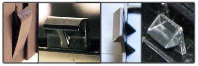
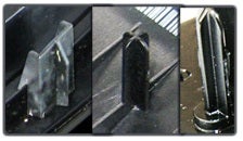
Lug – extension of plastic part which serves for securing the part. To be released from / affixed against other part or in a dedicated opening;
Clip lug – lug with metal clip on it which serves for securing the part. To be pulled out of / pushed back into a rectangular opening
Alignment lug - extension of plastic part which serves for aligning the part, but doesn’t secure it.
Centre console lower trim
If you’re doing the following in the midst of winter, you might be willing to keep the engine and heating running for some time in order to warm up interior prior to removal so that trim plastics are more flexible.
Gear lever gaiter surround
Step(1): Manual transmission
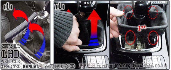
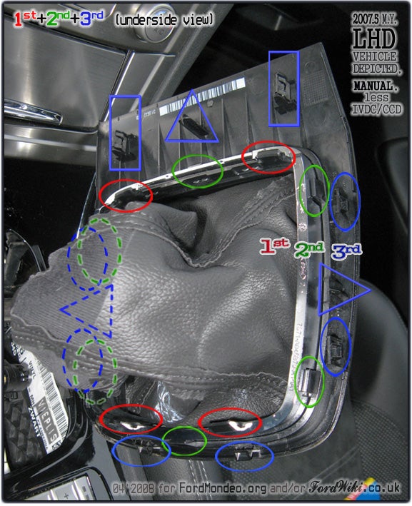
Gear lever gaiter surround consists of 3 separable pieces.
1st piece is the easiest to remove, with least likely occurrence of damage to any lugs.
Gaiter is stapled to the 1st piece. It has only 4 lugs which secure it against the bottom edge of 2nd piece.
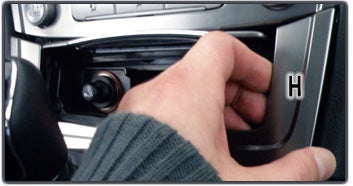
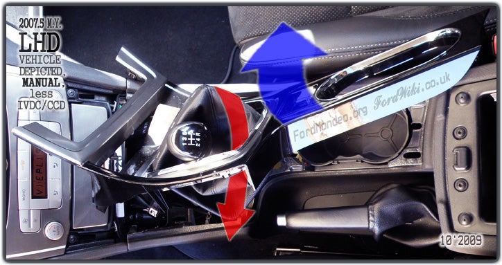
The following picture displays releasing 2 lugs at cup holders side, but you may as well start with releasing 2 lugs at ashtray side.
(1) Grasp the 1st piece with forefinger and thumb and pull up. Whilst doing so, gently force it towards the gear lever to ease releasing of 2 lugs.
Don’t worry if 2nd and 3rd piece happen to come out partly or fully whilst doing so, just pay attention to lugs and openings thus affected.
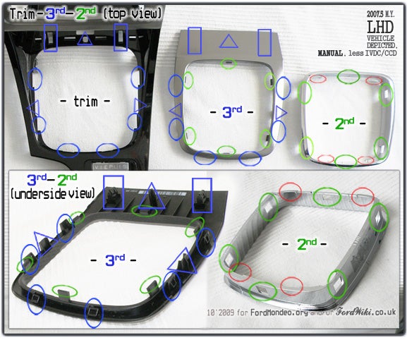
2nd piece has 6 openings where 6 lugs from 3rd piece come in and secure the 2nd piece.
3rd piece has 17 lugs. 11 lugs (including 6 lugs, 2 clip lugs and 3 alignment lugs) secure 3rd piece against the centre console lower trim; another 6 lugs “emanating” from 3rd piece secure the 2nd piece.
[Click for full-size version of the below image].
Repeated text:
1st piece has 4 lugs which secure it against the bottom edge of 2nd piece.
2nd piece has 6 openings where 6 lugs from 3rd piece come in and secure the 2nd piece.
3rd piece has 17 lugs. 11 lugs (including 6 lugs, 2 clip lugs and 3 alignment lugs) secure 3rd piece against the centre console lower trim; another 6 lugs “emanating” from 3rd piece secure the 2nd piece.
If necessary for hunt of rattles, 2nd and 3rd piece can be separated from the lower trim either at this point or later, after whole lower trim is removed completely.
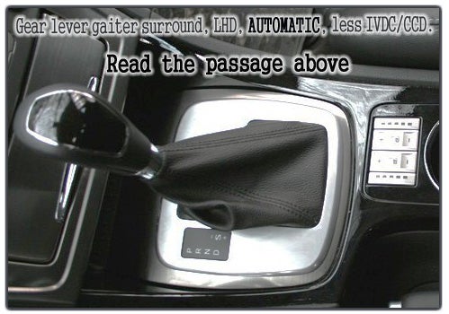
Step(1): Automatic transmission
Assuming the gear lever is in P (Park), make sure the parking brake is on. Turn on the ignition, but not the engine (if it's running, turn it off, and turn the ignition back on). Hold the brake pedal down, and put the gear lever in D (Drive). Turn off the ignition, and get cracking…
Lift the gear lever gaiter surround, ideally using a plastic flat-bladed trim removal tool. Take care not to bend or break any of the plastic clips that hold the surround in place. Disconnect the ribbon cable that goes to the shifter position legend. Take care not to bend or break the plastic stretch relief tab on the underside of the surround, that holds the ribbon cable in place.
The outer surround is the same as that of a manual transmission. The lid with the shifter legend has the same outer measurements and snap fittings as the outer ring of the manual gaiter.
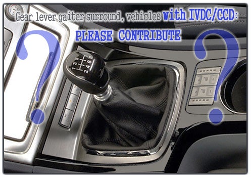
Step(1): Active suspension (IVDC/CCD)
(1) Remove the lever gaiter surround. Please contribute with details.
Step(2): Heated seats switch
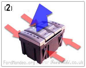
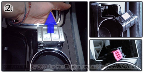
(2) Vehicles with heated seats:
- reach the switch through gear lever opening;
- disconnect the wiring connector and/or
- remove the switch.
In case of failure to unplug the connector with switch still in place, remove the switch and then unplug the connector. The switch has 4 lugs (2 per front and rear side), the edges of which rest against underside of the trim.
It is nearly impossible to press all 4 lugs and simultaneously push the switch up with one hand through gear lever opening. Instead, you can either simply push the switch up from underneath (I’ve been doing so many times and the lugs are still intact) …
… or put this step aside until the first lugs of the trim are released and reach the connector and/or the switch with fingertips from the front (gear lever opening) and from the rear (narrow gap between the trim and the base of cup holders).
Steps(3)-(4): Trim
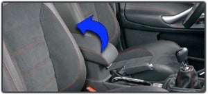
Open the storage compartment lid in order to facilitate next steps.
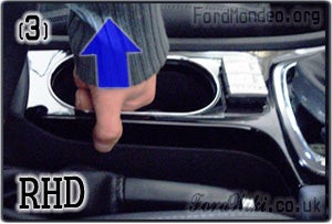
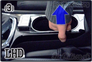
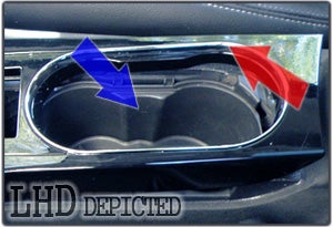
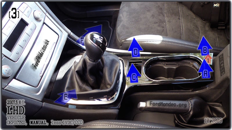
(3) Pull the trim up: grasp lip of the trim with forefinger and thumb near cup holders at handbrake side and gently pull up.
RHD vehicles:
LHD vehicles:
Base of cup holders will stay in place whilst pulling up. Don’t worry if the cup holders’ top surround plastic pops out – it doesn’t matter, place it back or remove temporarily.
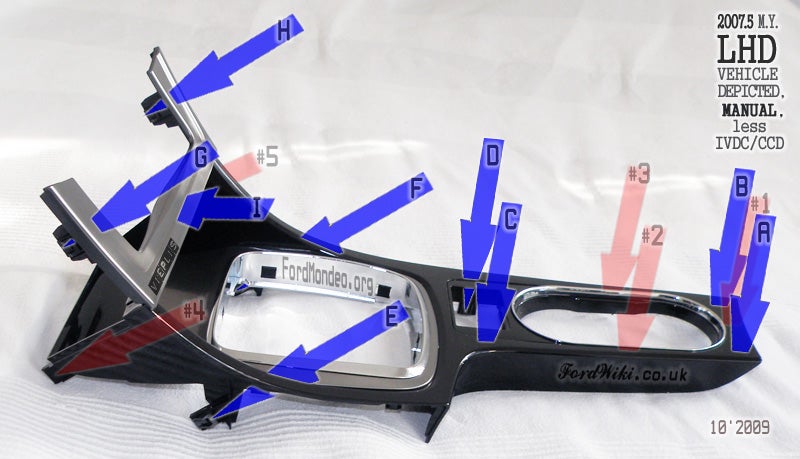
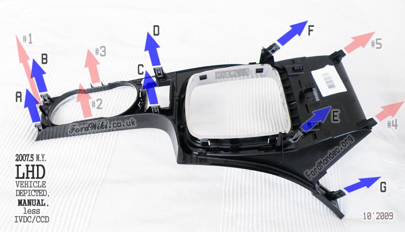
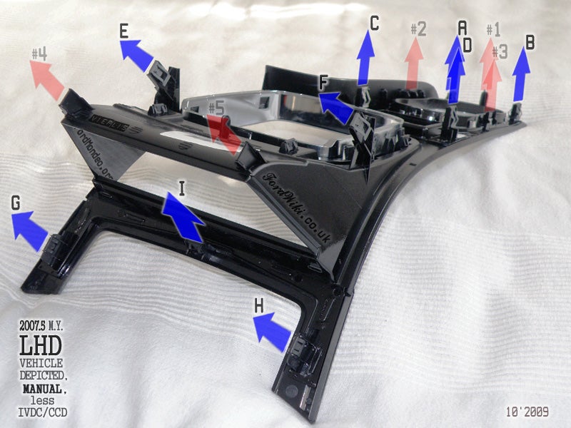
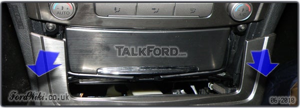
Aim of step (3) is to release clip lugs A, B, C and D, as well as alignment lug #1. Clip lugs C and D can also be accessed through gear lever opening or heated seats switch opening and released by pushing up with fingertips. You may also happen to [partly] release clip lugs E and F.
Disconnect the heated seats switch connector, if you haven’t already done so.
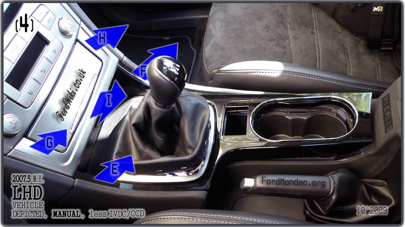
(4) Pull the trim rearwards. Aim of step (4) is to release clip lugs E, F, G, H and I.
Alternatively, it is possible to:
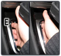
- access clip lugs E and F from underneath through gear lever opening and push them up (i.e., release) with fingertips;
- open the ashtray cover and pull the trim off with fingertips (i.e., release clip lugs I, G and H).
The trim has 13 lugs: 9 clip lugs and 5 alignment lugs.
Alignment lug #1 rests in a dedicated opening; alignment lugs #2 and #3 mate with cup holders base.
#4 and #5 seem to serve no purpose. Nevertheless, they’re marked as alignment lugs in this description, just in case if they actually do.
Step(5): Active suspension (IVDC/CCD) switch
(5) Vehicles with Active suspension (IVDC/CCD): unplug the switch wiring connector(-s). Please contribute with details and/or picture.
Once all lugs of the trim are released, 2 Torx TX20 screws underneath top edges of the lower trim will be revealed. They secure the upper trim.
The lower trim may either stay in place or be moved away completely. If not removed, leave space for Torx screw base tabs of upper trim which will have to move forward.
Complete removal of the lower trim requires pushing gear lever gaiter surround through trim opening. Keep an eye on sharp edges, lugs and clips of the trim whilst doing so in order to avoid damaging A/C screen, head unit, ashtray and/or upper trim.
Centre console upper trim
Correlation of the upper trim and head units/ navigation units.
- 6000CD – trim "sits on" unit. Access to unit requires complete removal of upper trim;
- Sony – same as 6000CD;
- TravelPilot FX (oval) – same as 6000CD;
- DVD Navigation NX – trim "sits on" unit and is affixed to it with screws. Omit step (8); proceed to DVD Navigation NX after step (7);
- Travel Pilot EX (rectangular) – unit "sits on" trim. Removal of unit does not require removal described in steps (1) to (8). However, removal of upper trim (for removal of ashtray etc.) has to be preceded by removal of unit.
Step(6): Triangles; Ignition button
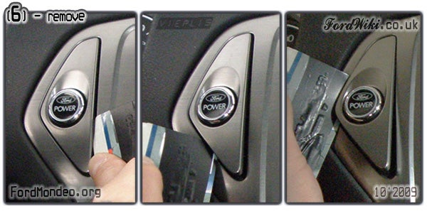
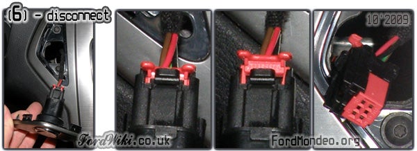
(6) Remove the plastic triangles with expired payment card or trim removal tool.
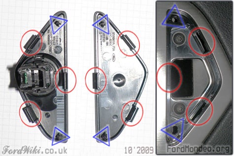
Each triangle is secured by 3 lugs and 2 alignment lugs.
Vehicles with keyless start (ignition button): disconnect wiring connector of ignition button.
Steps(7)-(8): Trim
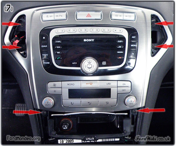
(7) - Vehicles with 6000CD, Sony, TravelPilot FX (oval) and DVD Navigation NX.
Undo 6 Torx TX20 screws – 4 in triangles and 2 adjacent to upper corners of ashtray. To prevent screws from finding their way into depths of console, you might be willing to cover openings in triangles with masking tape.
Vehicles with DVD Navigation NX: skip step (8) and proceed to DVD Navigation NX.
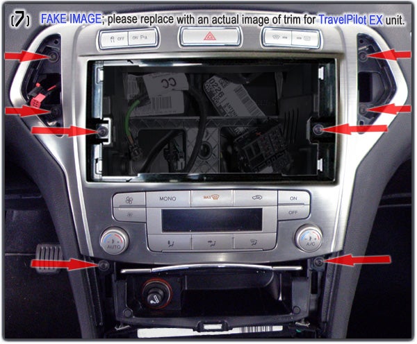
(7) - Vehicles with TravelPilot EX (rectangular).
Undo 8 Torx TX20 screws. Please contribute with details and/or authentic picture.
(8) All vehicles except those with DVD Navigation NX:
- pull trim forward, as far as connectors’ wiring allow;
- unplug connectors of top row switches (ESP or ESP+park assist switch, hazard warning switch, heated windows switch).
Vehicles with automatic climate control (DEATC):
- unplug 2 wiring connectors.
Remove the trim.
Head unit
Steps(9)-(11): 6000CD
Please contribute with details and/or picture(-s).
Procedure for 6000CD is analogue to Sony.
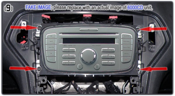
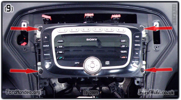
(9) Undo 4 screws. (Torx TX20)
(10) Pull the unit forward.
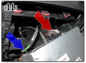
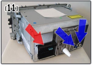
(11) Disconnect antenna connector and quadlock connector.
Remove the unit.
Steps(9)-(11): Sony
(9) Undo 4 Torx TX20 screws.
(10) Pull the unit forward.
(11) Disconnect antenna connector and quadlock connector. (Please contribute with details about connectors for Sony models with 6CD changer and/or with DAB.)
Remove the unit.
Please contribute with details and/or picture(-s).
Procedure for TravelPilot FX is analogue to Sony, bar the number of connectors.
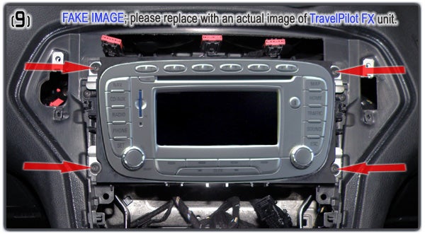
(9) Undo 4 screws. (Torx TX20)
(10) Pull the unit forward.
(11) Disconnect 2 antennae connectors and quadlock connector.
Remove the unit.
Please contribute with accurate details and authentic pictures.
Tools needed:
- set of Ford audio unit removal keys (GV3301);
- TX Torx? PH or PZ cross-head? Other?
(9) Remove the blanking plates
(10) Insert keys in dedicated openings adjacent to corners of the unit. Make sure you insert them correctly, so that they release the unit securing mechanism.
(11) Grasp either pair of the keys and pull the unit forward, as far as connectors’ wiring allow. Unit is affixed to trim, therefore both will come out as a whole.
[To be confirmed:] If you're doing this exercise for removal of ashtray, you may proceed to Ashtray if wiring allows. If not, disconnect at least 3 connectors of switches in trim (see next step).
(12) Disconnect wiring connectors.
- Start with connectors of 3 switches in trim (ESP or ESP+park assist switch, hazard warning switch, heated windows switch);
- continue with 5 connectors of the unit (2 antennae connectors, 1 quadlock connector, 2 climate control connectors).
Remove trim and unit.
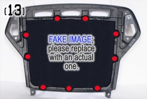
(13) Undo 9 screws (TX Torx? PH or PZ cross-head? Other?).
Separate the unit from the trim.
Please contribute with details and/or authentic picture(-s).
Tools needed: set of Ford audio unit removal keys (GV3301).
(0.a) Insert keys in dedicated openings adjacent to corners of the unit. Make sure you insert them correctly, so that they release the unit securing mechanism.
(0.b) Grasp either pair of the keys and pull the unit forward.
(0.c) Disconnect 2 antennae connectors and quadlock connector.
Remove the unit.
Ashtray
Change of ahtray bulb requires removal of whole ashtray unit.
Vehicles with 6000CD, Sony and TravelPilot FX (oval) – removal of ashtray doesn't require removal of head unit, and vice versa.
Vehicles with DVD Navigation NX - removal of ashtray requires the centre console upper trim to come forward [at least partially]. See steps (9) to (11) of section DVD Navigation NX.
Vehicles with TravelPilot EX (rectangular) - removal of ashtray requires removal of unit.
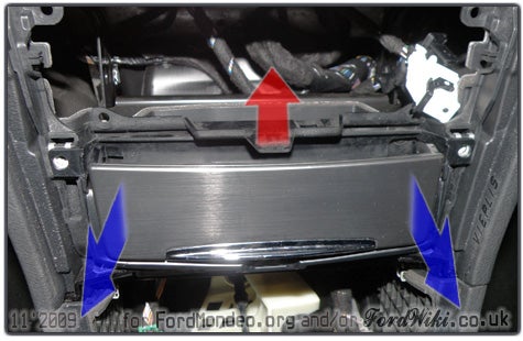
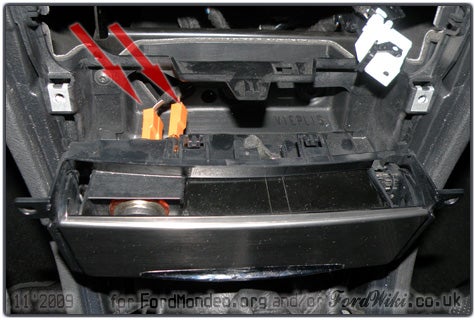
- Lift up tab and pull ashtray unit forward.
- Disconnect wiring connectors.
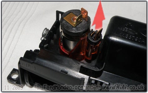
- Remove ashtray unit.
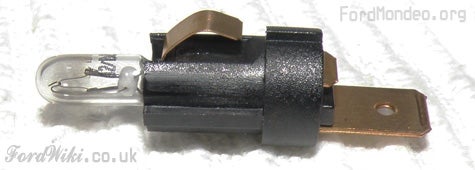
- Remove bulb socket from ashtray unit.
Bulb type?
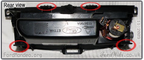
Visual 'inspection' of ashtray unit and its affixing method suggests that it should not cause squeaking or rattling. Nevertheless, here's a description of how it is affixed.
Lifting up the tab (see above) helps to release 4 lugs ...
... from dedicated openings ...
... and ashtray unit can be pulled forward easily.
Climate control switch
For all vehicles, bar those with DVD Navigation NX.
Vehicles with 6000CD, Sony and TravelPilot FX (oval) – removal of climate control switch doesn't require removal of head unit, and vice versa.
Vehicles with TravelPilot EX (rectangular) - removal of climate control switch requires removal of unit.
Manual
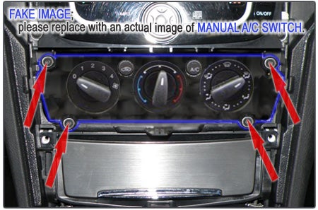
Removal of manual climate control switch. Please contribute with accurate description and/or picture(-s).
- Undo 4 screws. (TX Torx? PH or PZ cross-head? Other?)
- Pull the switch forward.
- Undo all connectors from the rear of the switch. (Details?)
- Remove the switch.
Automatic
Removal of automatic climate control (DEATC) switch.
- Undo 4 screws (PZ2 cross-head).
- Remove the switch.
Trim for oval head unit (6000CD, Sony, TravelPilot FX) is depicted in image, yet the procedure is analogous on trim for rectangular TravelPilot EX.
Headlight switch
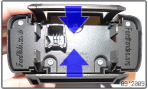
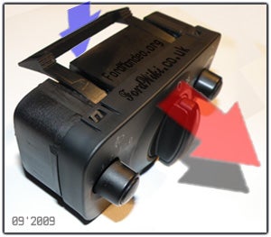
In order to remove the switch, access it from the back, squeeze horizontal bars to release it ...
... and push it forward.
Access and removal:
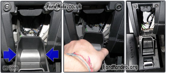
- open the small storage 'drawer' down below the switch;
- squeeze it in order to open it further;
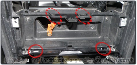
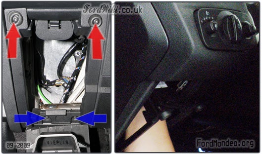
You may now try to access switch from the back side. If you find that OBD port wiring and connector stand in the way:
- undo all 4 Torx TX20 screws that secure frame of storage 'drawer' (there's little available space for undoing 2 lower TX20 screws; it may require compact right angle socket in combination with a Torx bit),
- disconnect OBD port connector and
- remove storage 'drawer' frame completely.
Alternatively, undo only 2 upper TX20 screws and let the storage 'drawer' frame bear some bending during the following steps.
- Access the switch, squeeze the bars and push it out.
- Disconnect wiring connector and the switch is yours.









 Your Privacy Choices