Registrations
We now manually approve all new user accounts due to a large influx of spam bots. Accounts are normally approved within 48 hours.
If you need any help with using this Wiki, please ask here: TalkFord.com Wiki Submission Forum
Folding Mirrors With Remote Key
For more information, visit the Ford Mondeo forum on TalkFord.com, the definitive resource site covering all Fords from the present day to the 1970's.
|
Courtesy of TalkFord.com | |
| Author: | fordy1 |
|---|---|
| Ford Model: | Mondeo Mk3 |
| Estimated Cost: | Free |
| Difficulty? | Medium |
| How long does this take? | 1 hour |
| Licensing: |
|
Contents
Folding Mirrors With Remote Key - Mk3
Background
The following article works for the 2003¾ model Mondeo. The plan is that when you exit your vehicle and apply the double lock with the remote key, the electrically folding mirrors will fold in and when the car is reopened, they will unfold.
I have attached a few images in order to assist anyone who is thinking of trying this. I have it up and running in my car for the last week and have had no problems. I had a habit of pressing the locking switch on the key remote several times consecutively. This can cause extra signals being sent to the mirror folding module with the result of the mirrors unfolding accidentally. Not to worry though - the sequence will sort itself out after a couple of set/reset operations.
Firstly I hasten to point out that I am not a mechanic or an electrical engineer. My work is all on a hobby and challenge basis... if you get my drift.
Parts
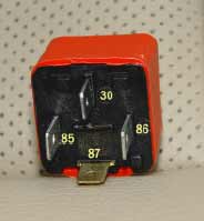
A standard 12v auto relay that has at least 4 pins numbered 30, 85, 86 and 87. When current is passed between 85 and 86, contacts 30 and 87 are joined.
Some lengths of wire. I visited my ever-helpful Ford dealer who recovered a damaged wire loom from a skip. This was a partially burned dash wire loom from a Transit. This is ideal as you can use multicolored wire in keeping with the original color code scheme of the car.
Assortment of tools, soldering iron and a circuit tester. I have a pen-type one with a small bulb installed in the body of it.
Theory
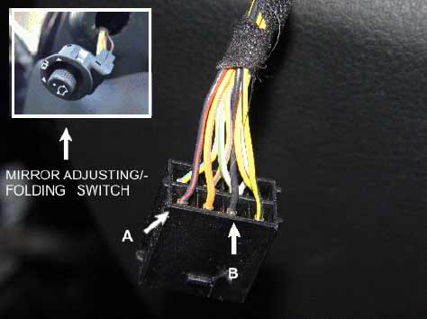
The mirrors folding motors are operated by using the mirror direction adjusting switch located at the driver’s door. With the switch in the centre position (ie neither left nor right mirror selected, tip the switch downwards (6 o'clock position) to fold and the same again to unfold. This action by the switch causes 2 wires on the connector block attached, to join. The wires are colored red/black and black. They are marked A and B in the picture. There is no need to root out this switch unless you’re curious.
Preparation
On the passenger’s side, open and remove the glove box. This job is simple in theory but gentle persuasion is required. Be careful not to break the retaining clips - they’re only plastic. If they do break, they are available at the main dealer.
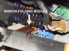
Once the glove box is removed, the fuse box is clearly visible. The mirror folding module, (or if you want to call it, relay) is brown in color and is located under the main fuse rack.
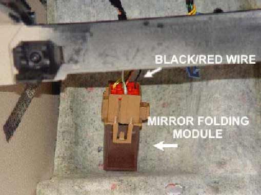
Remove the insulation pad from under the fuse rack. With a small flat screwdriver, remove the blue connector first and then the brown connector. They just slide on, but there is a retaining lip which prevents the connector from sliding off. A small inspection torch is useful at this time. The mirror module should drop down for closer inspection. The wire that is required is the black/red one.
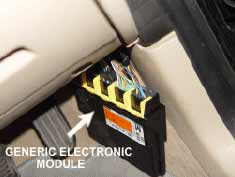
To the drivers side now and remove the small drawer at your right knee. Now get down on the floor and locate the general electronic module. It is on the right hand side of the floor just above, and to the right of the accelerator pedal.
Examine this module. It has 5 connectors or plugs going into it. Anyone who has the Ford wiring diagrams can trace these down with each of the plugs numbered. These are C430, C429, C426, C428 and C427. Our interest is in C427, arrowed number 1. I edited the picture and printed the numbers on the plugs to clarify. There are plastic caps or cover on these 5 plugs. The picture shows them having been removed. There is only the need to remove the cap from C427. I took them all off when I was researching the project. In reality, the actual plugs are not marked. A different view of C427 is inset in the following image with a yellow wire marked number 2. When the remote is pressed for the second time to double lock the doors, a positive current or pulse of power, comes through this wire. If the remote key is pressed once, ie normal locking, then no current comes through. When the remote key is pressed to unlock the doors, current comes through this wire. To test this first, get back into the car and shut all the doors. Stick one end of the circuit tester into the yellow wire 2 and earth the other end to any exposed metal body area.
Double-lock the car with the remote key and the test lamp should light up briefly. Then unlock the car with the remote and the lamp should light once more.
At this stage you should be familiar with the different components. There is no harm in disconnecting the car battery as a precaution. Note: make sure you have your radio security code saved somewhere!
Procedure
Take an additional wire and join it to the yellow wire (number 2, in pic 6). You can cut the yellow and splice it in, you can use crimp connectors or what ever is your preference. Personally I try to avoid cutting wire looms unless it is necessary. I peeled back the additional wire, partially soldered it and packed the ends in around the connector and then used small cable ties to secure it. I used twin yellow wire as I had not wire of the same gauge handy.
Connect the new wire to contact 85 on the relay in Pic 1. Take another wire from contact 86 on the relay. This will be earthed at a later stage.
Take a long piece of wire and run it from the driver’s side to the fuse box area. A straightened wire coat hanger or thin welding rod is a great tool for such work. Wrap a piece of insulating, masking or gutter tape around the point to reduce damage by scratching, etc. I passed the wire along the back of the radio/heater area. There is a large re-enforcing iron tube running from the driver side to the passenger side inside the dash assembly. I found this a good source of guidance for this part of the job.
Attach this wire to the black/red wire on the folding mirror module, Pic 4
Attach the other of this wire to contact 30 on the relay in Pic 1
Get 1 more short length of wire and attach it to contact 87 on the relay in Pic 1
Wires from 86 and 87 can be crimped into an eyelet terminal. These will be earthed
Drill a small hole in any body metal point. I used the metal reinforcing tube mentioned above. Pass the self tapper screw into the eyelet terminal and through the relay fixing point to ensure a good earth connection.
Ready to test now. Reconnect the power lead to the car battery, and close the car doors and bonnet.
Press the remote key once to lock and immediately a second time to double lock. The mirrors should fold in. Press the unlock once and the mirrors should unfold.
Submitted by fordy1


 Your Privacy Choices