Registrations
We now manually approve all new user accounts due to a large influx of spam bots. Accounts are normally approved within 48 hours.
If you need any help with using this Wiki, please ask here: TalkFord.com Wiki Submission Forum
Quadlock Stereo Connector - Sony DAB / USB
|
Overview Guide | |
| Ford Model: | Mondeo / Focus / Galaxy - Sony DAB CD Audio system with USB / iPod input |
|---|---|
| Petrol/Diesel: | ???? |
| Estimated Cost: | ???? |
| Difficulty? | ???? |
| How long does this take? | ???? |
Note: This wiki article is based on the "Quadlock Stereo Connector - Facelift" article. I've added some additional information based on removal of the SONY DAB CD head unit from my 2010 registered Ford Galaxy. There are lots of gaps, guesswork and ommissions, and it really needs someone with an offical Ford wiring diagram to update it properly, but it's better than the older article if you have one of the more recent Ford models with the Sony DAB CD unit. I suspect the information is accurate for all Ford Models, but have only checked it against my Galaxy.
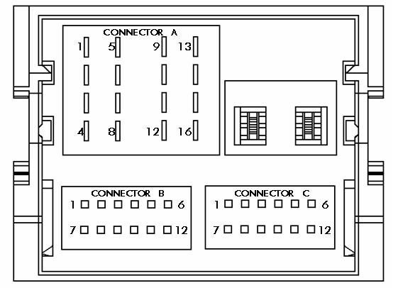
The following figure illustrates the connector layout and gives pin numbers which correspond to the lists below.
The colours given are for the wiring loom from the quadlock connector and follow through the card to the speakers / aux sockets. "not used" indicated there was no connection in my car, but this might be because there is a feature I don't have installed.
Contents
Connector A (C517/C518)
Speakers (C517)
Pin 1 Right Rear + (brown/white)
Pin 2 Right Front + (purple/white x2)
Pin 3 Left Front + (white x2)
Pin 4 Left Rear + (brown/green)
Pin 5 Right Rear – (brown/blue)
Pin 6 Right Front – (orange/white x2)
Pin 7 Left Front – (white/brown x2)
Pin 8 Left Rear – (brown/yellow)
Power (C518)
Pin 9 CAN + (blue/white)
Pin 10 CAN – (purple)
Pin 11 Keycode Ground (black/blue)
Pin 12 Ground (black/blue)
Pin 13 Alarm Sense (From GEM) (yellow/grey)
Pin 14 Illumination (not used)
Pin 15 Battery + (From F72) (brown/red)
Pin 16 Ign. Sense (Accessory) (From F69) (not used)
Connector B (C520)
Pin 1 Mono + (not used)
Pin 2 Sw A+ (Switched Output (On when stereo is on) - Used with Rear Seat DVD's or 3rd party amplifier switch) (green/purple)
Pin 3 Aux L+ (CD Changer) (not used)
Pin 4 Aux R + (CD Changer) (not used)
Pin 5 PTA (Phone Mute) (not used)
Pin 6 SWC (Steering Wheel Controls) (grey/yellow)
Pin 7 Mono - (not used)
Pin 8 SWC Gnd (Steering Wheel Controls) (blue)
Pin 9 Aux L – (CD Changer) (not used)
Pin 10 Aux R – (CD Changer) (not used)
Pin 11 Rev Sense (Used for Navigation) (not used)
Pin 12 AVC - Speed signal for Auto Volume Control (not used)
Connector C (C519)
(NB: I believe several of the descriptions here are incorrect - I think most of them are for the USB socket in the glovebox, but I didn't follow the wiring round the car to check this)
Pin 1 RSE L+ (Rear Seat Entertainment) (green)
Pin 2 RSE R+ (Rear Seat Entertainment) (not used)
Pin 3 Mono 2 + (brown/red)
Pin 4 Sub W + (not used)
Pin 5 Aux 2 L (Glovebox Aux Socket L) (white/purple)
Pin 6 Audio Gnd (black)
Pin 7 RSE L – (Rear Seat Entertainment) (grey/yellow)
Pin 8 RSE R – (Rear Seat Entertainment) (not used)
Pin 9 Mono 2 – (blue/red)
Pin 10 Sub W – (blue)
Pin 11 Aux 2 R (Glovebox Aux Socket R) (yellow/blue)
Pin 12 Mic. (brown)
Wiring to 3rd party amplifier / active subwoofer enclosure
There is no "line level" output on the Sony DAB CD audio units (the type of signal normally provided on RCA / Phono connectors to go into the input of an Amp). This means that for the audio input into the amp you will need to use the high-level signal from the rear speakers and either feed it into the high-level input of your amp (if it has one) or purchase a separate high-level to RCA converter box (available from car audio stores).
The one wire you will require from the quadlock connector is pin 2 from connector B - the green/purple switched output. This carries +12v when the stereo is switched on, and 0v when the stereo is switched off. This should be fed to the switch input on your amp so that the amp switched on and off when your stereo switched on and off. This prevents the amp draining your battery when you're not listening to music. Note that if you listen to music loudly without the engine running, you'll risk draining your battery anyway!
Luckily this pin is already in use and so you can easily splice into the green/purple wire with a crimp connector. It is relatively easy to run this wire from behind the stereo to the back of the glove box where the main wiring loom comes into the chassis from the engine bay. This is a good point to run your +12v power lead from the battery into the car through the huge rubber grommit that carries the rest of the loom. The switch wire and power wire can then both be routed to the boot under the door sill trims before going up the wheel arch trim to the rear speaker points. This makes for a very neat job.

 Your Privacy Choices